Uh oh.. I have a box from Digikey!
Oh.. My... Gawd... This things are TINY!
But they are so CUTE!
Uh oh.. I have a box from Digikey!
Oh.. My... Gawd... This things are TINY!
")
Add a USB or electron microscope to that list in the other thread...
Excellent job Nico, I just picked up a gallon of muratic acid for etching my PCB board, am going to try an make some small touch boards but use a micro switch. I also am looking at adding a power fan with the motor below in the picture
16,000 rpm at 3vdc.
Again great job!
Dan

Uh oh.. I have a box from Digikey!
Oh.. My... Gawd... This things are TINY!
You did train your pet gnat to solder right?Add a USB or electron microscope to that list in the other thread...

Sweet.... I assume the PCB has predrilled holes? Shoot, knowing you, you drill your own holes with a drill that you made and drill bits that you carved, after mining the ore and smelting it...
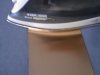
Lots of pools in my neighborhood - so lots of Muriatic acid (Fun stuff.. Don't breath the fumes or get it on you!)


Correct me if I'm wrong - but wouldn't this save you one solder point?
(I'm not sure which thread I pulled it from) - but you have two grounds...
View attachment 11599
View attachment 11600
( I added a line between 'S' and 'D')
I added B for battery, T for touch points, and A for atty.Okay...
This is one of those "Way too long" things to explain on the boards I'm thinking..... I will just go with "No. BAD."
Unless S and D are in/out puts on the MOSFET and shouldn't be tied together...
(Add "take Electronics class" to that list.....)
LOL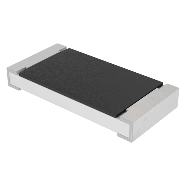

Sweet.... I assume the PCB has predrilled holes? Shoot, knowing you, you drill your own holes with a drill that you made and drill bits that you carved, after mining the ore and smelting it...
Lots of pools in my neighborhood - so lots of Muriatic acid (Fun stuff.. Don't breath the fumes or get it on you!)

No, Bad
Hey I ordered some surface mount resistors rather than the through hole resistors, it will make the chip even smaller. Here is what I am talking about:
They are tiny and do the same thing as this:
Thought I might share this with you, as they are both 47k ohm resistors but the surface mounts are tiny!
They are also called flat chip resistors:
Flat chip resistors (Anti-sulfuration) - Surface Mount Resistors - Resistors - KOA Speer Electronics, Inc.
Dan
 Just make sure you dont throw them away when you open the box and dont see anything!!
Oh here is a sample of the concept for the fan, this could be connected directly to the bottom of the atty connector on the inside of your mod Nico. This would allow the user such as someone with CPOD or other respratory affliction to just inhale with out having to suck so hard and get nothing.
Will be in testing soon.
Dan
That mod looks great Nico. Thanks for painting it to match my truck.
Damn leaky paint cans ya know!!
Thanks 42109...matches my 74 Cuda in the garage too!
It would match my sons 71 Cuda model car he is working on too...but he may not have enough paint when he goes for it!!!
Oh yeah...get the little resistors he says!!
Would that fan be pushing or pulling on the vape Dan? Almost have to be pushing due to the fan getting gunked up and centrifugal force spinning the juice against the sides.
Keep us enlightened!!